


1.1 Definition of Deadlock
1.1.1 Process-Level Interpretation
Explanation:
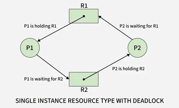
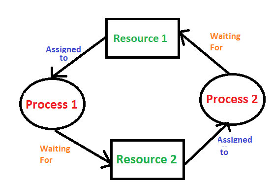
At the process level, a deadlock is a state where two or more processes cannot continue execution because each one is waiting for a resource held by another process. This creates a cycle of dependencies where no process can proceed, resulting in permanent blocking.
The key characteristic is dependency chaining, where each process is holding one resource and waiting for another. Since every involved process is blocked, the system cannot resolve the conflict without external intervention.
Example:
Process P1 holds Resource R1 and waits for Resource R2.
Process P2 holds Resource R2 and waits for Resource R1.
Both remain blocked indefinitely.
Table
| Process | Resource Held | Resource Needed | Status |
|---|---|---|---|
| P1 | R1 | R2 | Waiting |
| P2 | R2 | R1 | Waiting |
Use Cases
Multi-process applications requesting I/O devices
Processes locking files in inconsistent orders
Parallel applications requiring exclusive resource access

1.1.2 Resource-Level Interpretation
Explanation:
From the resource perspective, a deadlock occurs when resources cannot be allocated because they are already held in a way that prevents further distribution. Resources are locked in cycles, and the system cannot preempt them safely, causing an indefinite wait.
This interpretation focuses on resource allocation states rather than processes.
Example:
Printer is held by Process P1.
Scanner is held by Process P2.
Both require the other resource to complete execution.
Table
| Resource | Current Owner | Requested By | Availability |
|---|---|---|---|
| Printer | P1 | P2 | Locked |
| Scanner | P2 | P1 | Locked |
Use Cases
Operating systems handling device queues
Database resource managers coordinating locks
Virtual machines managing shared peripherals
1.2 Importance of Studying Deadlocks
1.2.1 Impact on CPU Utilization
Explanation:
Deadlocks significantly reduce CPU utilization because blocked processes consume no CPU cycles yet hold critical resources. When multiple deadlocked processes exist, CPU idle time increases, even though runnable tasks are indirectly waiting due to locked resources.
In high-throughput or real-time systems, deadlocks can cause severe performance degradation.
Example:
A deadlocked I/O operation results in dependent processes being blocked, leaving the CPU idle despite pending work.
Table
| Condition | CPU Activity | Impact |
|---|---|---|
| No Deadlock | High utilization | Efficient execution |
| Deadlock | Low utilization | CPU idle due to blocked tasks |
Use Cases
High-performance servers
Real-time operating systems
Cloud systems requiring consistent resource availability
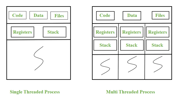
1.2.2 Impact on Multi-threaded Applications
Explanation:
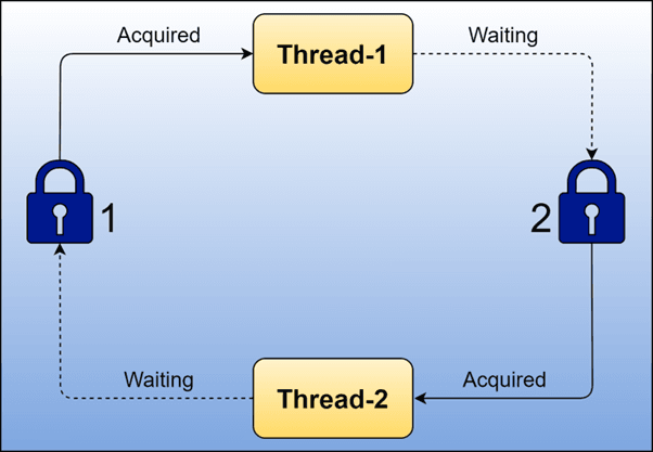
Deadlocks pose higher risks in multi-threaded programs because threads share resources such as memory segments, mutexes, semaphores, and critical sections.
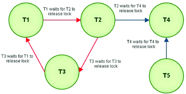
Improper lock ordering or simultaneous requests can create a circular wait, freezing application modules. These issues are difficult to debug because they occur at runtime, not compile time.
Example:
Thread T1 holds Lock A and waits for Lock B.
Thread T2 holds Lock B and waits for Lock A.
The application stalls completely.
Table
| Thread | Lock Held | Lock Requested | Outcome |
|---|---|---|---|
| T1 | A | B | Blocked |
| T2 | B | A | Blocked |
Use Cases
Banking transaction systems
Gaming engines with parallel threads
Multithreaded file processing systems
1.3 Real-World Deadlock Scenarios
1.3.1 OS-Level Example
Explanation:
At the operating system level, deadlocks occur when processes request exclusive devices such as printers, tape drives, or memory blocks simultaneously. Improper allocation may create a circular wait condition, freezing kernel components.
Example:
Process P1 locks a hard disk controller and waits for a network card.
Process P2 locks the network card and waits for the hard disk controller.
Use Cases
File system operations with nested locks
Kernel modules accessing shared drivers
Low-level I/O scheduling
1.3.2 Database-Level Example
Explanation:
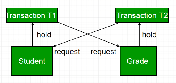
Databases encounter deadlocks when transactions lock tables, rows, or indexes in opposite orders. Most Database Management Systems (DBMS) detect deadlocks and abort one transaction to break the cycle.
Example:
Transaction T1 updates Row A then requests Row B.
Transaction T2 updates Row B then requests Row A.
Table
| Transaction | Locked | Waiting For | Status |
|---|---|---|---|
| T1 | Row A | Row B | Blocked |
| T2 | Row B | Row A | Blocked |
Use Cases
Banking systems updating balances
E-commerce inventory updates
ERP systems managing concurrent transactions
1.3.3 Distributed System Example
Explanation:
In distributed systems, deadlocks span multiple machines. Resource requests across network nodes increase the risk of cyclic dependencies. Detection becomes difficult because no single system has a global view of resource ownership.
Example:
Node A waits for a lock held by Node B.
Node B waits for a lock held by Node C.
Node C waits for a lock held by Node A.
A global deadlock forms across the network.
Use Cases
Distributed databases with lock managers
Microservices using cross-service transactions
Cloud-based distributed file systems
2. Four Necessary Conditions for Deadlock
2.1 Mutual Exclusion
2.1.1 Hardware-Induced Mutual Exclusion
Explanation:
Hardware-induced mutual exclusion occurs when a physical resource cannot be shared between multiple processes. These resources include printers, CPUs, disk arms, tape drives, camera sensors, GPU units, and other exclusive hardware devices. Mutual exclusion exists inherently because such devices cannot perform operations for more than one process simultaneously. Since these resources lack shareability, they form the first and unavoidable pillar of deadlock formation.
Example:
A printer can print only one document at a time.
If Process P1 is using the printer, Process P2 must wait, creating an exclusive lock scenario.
Table
| Hardware Resource | Sharable? | Example Conflict | Deadlock Impact |
|---|---|---|---|
| Printer | No | P1 printing, P2 waiting | High |
| Scanner | No | P2 scanning, P1 waiting | Medium |
| Disk Controller | No | P1 doing I/O, P3 waiting | High |
Use Cases:
Print spooling systems
Hardware-level I/O schedulers
Device drivers requiring exclusive access
2.1.2 Software-Induced Mutual Exclusion
Explanation:
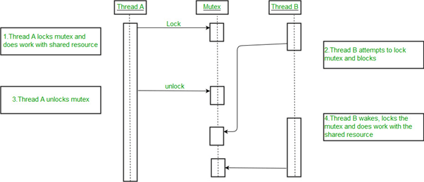
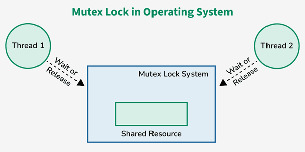
Software-induced mutual exclusion is created through synchronization constructs such as mutexes, semaphores, monitors, and critical sections. Although the underlying resources may be sharable, software mechanisms enforce exclusive access to maintain consistency. When multiple threads attempt to access shared memory or critical data structures, mutual exclusion prevents race conditions but increases deadlock risk.
Example:
Thread T1 holds Mutex A.
Thread T2 holds Mutex B.
T1 needs Mutex B while T2 needs Mutex A.
Both wait indefinitely.
Table
| Software Mechanism | Purpose | Deadlock Risk |
|---|---|---|
| Mutex | Exclusive lock | High |
| Semaphore | Count control | Medium |
| Monitor | Synchronization | High |
Use Cases:
Multi-threaded applications
Database row/record locking
OS kernel synchronization
2.2 Hold and Wait
2.2.1 Occurrence in Multi-Process Systems
Explanation:
Hold and Wait occurs when a process is holding at least one resource and simultaneously waiting to acquire additional resources. This condition naturally arises in multi-process systems where tasks request resources sequentially based on execution progress. If multiple processes behave similarly without strict allocation control, circular chains of dependencies form easily.
Example:
P1 holds R1 and waits for R2
P2 holds R2 and waits for R3
P3 holds R3 and waits for R1
Table
| Process | Resource Held | Resource Needed | Waiting? |
|---|---|---|---|
| P1 | R1 | R2 | Yes |
| P2 | R2 | R3 | Yes |
| P3 | R3 | R1 | Yes |
Use Cases:
Multi-step process workflows
Memory allocation during program execution
OS requiring multiple devices per process
2.2.2 Strategies to Mitigate
Explanation:
Hold and Wait can be reduced through specific OS allocation strategies, though each comes with trade-offs.
Mitigation Strategies:
Request all required resources at once
Require release of held resources before requesting new ones
Use dynamic resource allocation ordering
Apply timeouts for waiting
Example:
A process must request all needed devices upfront.
If not available, it waits without holding anything.
Table
| Strategy | Benefit | Drawback |
|---|---|---|
| Request-all-at-once | No deadlock chain | Poor resource utilization |
| Release-before-request | Avoids hold/wait | High overhead |
| Timeout-based | Prevents infinite wait | Risk of starvation |
Use Cases:
Cloud-based servers allocating multiple VMs
Batch processing systems
Database transactions requiring multiple locks
2.3 No Preemption
2.3.1 Why Preemption Is Not Always Possible
Explanation:
No Preemption means a resource cannot be forcibly taken away from a process until the process voluntarily releases it. Many hardware and software resources cannot be preempted due to consistency, transactional integrity, or hardware limitations. This condition increases deadlock risk because once a resource is allocated, the system cannot reclaim it even if another process needs it urgently.
Example:
You cannot forcibly stop a process in the middle of printing a document and take the printer away without corrupting output.
Table
| Resource | Preemptible? | Reason |
|---|---|---|
| CPU | Yes | OS scheduling |
| Printer | No | Output consistency |
| Disk I/O | No | Data integrity |
| Memory | Sometimes | Depending on OS design |
Use Cases:
Databases executing multi-step transactions
Printers executing long jobs
Processes performing file writes
2.3.2 Examples: Printer, IO Devices
Explanation:
Certain resources must run uninterrupted to ensure correct system behavior. Interrupting or preempting them mid-use will lead to corruption or incomplete execution.
Examples:
Printer cannot be stopped mid-page
Disk read/write operations must execute atomically
Network packets cannot be partially transmitted
Use Cases:
High-speed real-time I/O operations
Kernel-level drivers
Backup and restore operations

2.4 Circular Wait
2.4.1 Resource Ordering
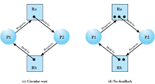
Explanation:
Circular wait occurs when processes form a cycle such that each process holds a resource and waits for another resource held by the next process in the cycle. One common method to prevent circular wait is by imposing a strict global ordering on resources, ensuring processes request resources only in ascending order.
Example:
Resources R1 < R2 < R3
If every process requests resources in this order, circular wait cannot form.
Table
| Process | Holds | Requests | Order Valid? |
|---|---|---|---|
| P1 | R1 | R2 | Yes |
| P2 | R2 | R3 | Yes |
Use Cases:
Large OS kernels controlling many devices
Data locking in databases
Distributed lock managers
2.4.2 Cycle Detection Logic
Explanation:
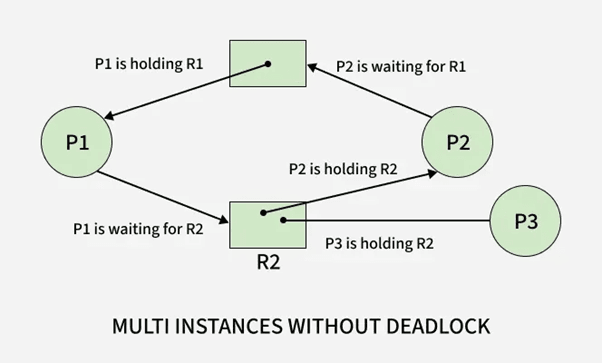
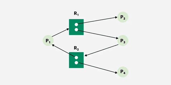
Circular wait can be identified using cycle detection in a Resource Allocation Graph (RAG). If a cycle exists in the graph, and each resource in the cycle has only one instance, a deadlock is guaranteed.
Example:
P1 → R1 → P2 → R2 → P1 forms a deadlock cycle.
Use Cases:
OS-level deadlock detection modules
Database wait-for graph algorithms
Distributed deadlock detection
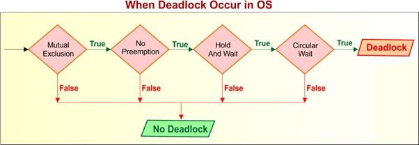
2.5 How These Conditions Combine to Cause Deadlock
2.5.1 Necessary vs Sufficient Conditions
Explanation:
All four conditions must hold simultaneously for a deadlock to occur.
They are necessary, but not individually sufficient.
Deadlock = Mutual Exclusion + Hold-and-Wait + No Preemption + Circular Wait
Table
| Condition | Needed? | Alone Causes Deadlock? |
|---|---|---|
| Mutual Exclusion | Yes | No |
| Hold and Wait | Yes | No |
| No Preemption | Yes | No |
| Circular Wait | Yes | No |
Use Cases:
OS designers validating safe state transitions
Deadlock analysis for multi-threaded systems
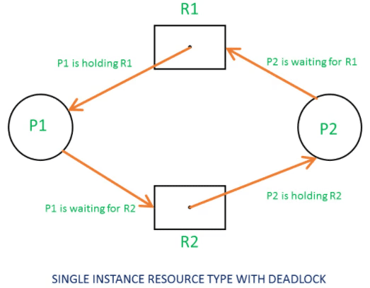
2.5.2 Real Example with RAG (Resource Allocation Graph)
Explanation:
A RAG visually represents processes and resources. A cycle indicates a deadlock.
For example:
P1 holds R1 and waits for R2
P2 holds R2 and waits for R1
Cycle: P1 → R2 → P2 → R1 → P1
Table
| Process | Holds | Wants | Result |
|---|---|---|---|
| P1 | R1 | R2 | Waiting |
| P2 | R2 | R1 | Waiting |
Use Cases:
Visual teaching of deadlock detection
OS kernel implementation
Distributed system deadlock debugging
3. Deadlock Handling Methods
3.1 Deadlock Prevention
3.1.1 Breaking Mutual Exclusion
Explanation:
Deadlock prevention aims to structurally eliminate one or more of the four necessary deadlock conditions. To break mutual exclusion, the OS attempts to make resources sharable wherever possible. Although many hardware resources must remain non-sharable, software-managed resources can often be redesigned to support concurrent access. This reduces the number of exclusive locks and minimizes the opportunity for circular dependencies to form.
Example:
Instead of exclusive file locks, the OS uses read-write locks allowing multiple readers concurrently, reducing mutual exclusion scenarios.
Table
| Resource Type | Original Behavior | Modified Behavior | Deadlock Impact |
|---|---|---|---|
| File | Exclusive lock | Reader-writer lock | Reduced risk |
| Memory | Locked per process | Shared memory segments | Reduced risk |
| Cache | Exclusive access | Multi-thread safe caching | Reduced risk |
Use Cases:
File systems allowing parallel read access
Shared memory with atomic operations
Replacing mutexes with lock-free data structures
3.1.2 Eliminating Hold & Wait
Explanation:
To eliminate Hold & Wait, processes must either request all required resources at the start or release held resources before requesting new ones. This ensures no process holds one resource while waiting for another. Although effective at preventing deadlocks, this approach often reduces system efficiency because resources may remain idle even when unused.
Example:
A print-and-save process must request both the printer and disk at the beginning. If unavailable, it waits without holding anything.
Table
| Strategy | Benefit | Drawback |
|---|---|---|
| Request-all-at-start | No circular wait possible | Poor utilization |
| Release-before-request | Avoids chained wait | High overhead |
Use Cases:
Batch processing systems
Programs that execute predictable multi-step operations
Real-time systems needing deterministic allocation
3.1.3 Allowing Preemption
Explanation:
Allowing preemption means the OS can forcibly take resources away from a process and reassign them when needed to avoid deadlock. Preemption works best for CPU time, memory pages, and logical locks but is not always applicable to hardware resources. The OS attempts to interrupt and roll back processes without compromising data integrity.
Example:
If P1 holds memory and waits for I/O, while P2 needs memory but holds the I/O device, the OS may preempt memory from P1, allowing P2 to proceed and later return memory to P1.
Table
| Resource | Preemptible? | Notes |
|---|---|---|
| Memory | Yes | Swappable |
| CPU | Yes | Scheduler controlled |
| Printer | No | Cannot interrupt prints |
| Disk operation | No | Integrity risk |
Use Cases:
Paging systems
Transaction rollback
Memory-managed multi-tasking systems
3.1.4 Breaking Circular Wait
Explanation:
To break circular wait, the OS imposes a strict global ordering of resource acquisition. Every resource is assigned a number, and processes must request resources in ascending order. This prevents cyclic dependencies because no process can wait for a lower-numbered resource while holding a higher-numbered one.
Example:
Resource ordering: R1 < R2 < R3
Processes must request R1 before R2, and R2 before R3.
Table
| Process | Holds | Requests | Valid? |
|---|---|---|---|
| P1 | R1 | R2 | Yes |
| P2 | R2 | R3 | Yes |
| P3 | R3 | R1 | No (disallowed) |
Use Cases:
Operating system device allocation
Database locking order policies
Distributed transaction systems
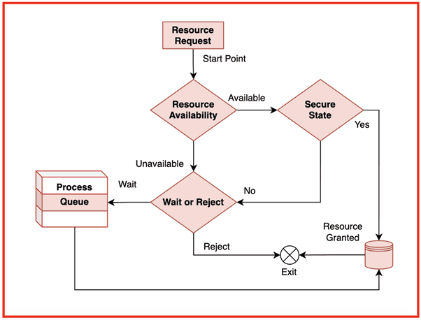
3.2 Deadlock Avoidance
3.2.1 Safe State Concept
Explanation:
A safe state is a system state from which all processes can complete their execution without causing deadlock. The OS evaluates whether allocating a resource will still leave the system in a safe sequence. If not, the allocation is denied. Safe states are crucial in avoidance algorithms, especially Banker's Algorithm.
Example:
If the system finds a sequence P1 → P3 → P2 that allows all processes to complete, the state is safe.
Table
| Process | Max | Allocation | Need | Safe? |
|---|---|---|---|---|
| P1 | 7 | 5 | 2 | Yes |
| P2 | 3 | 1 | 2 | Yes |
| P3 | 9 | 3 | 6 | Yes |
Use Cases:
Banker's Algorithm
Resource-aware real-time systems
Virtual machine scheduling
3.2.2 Unsafe State Concept
Explanation:
An unsafe state is not necessarily a deadlock but represents a condition where the OS cannot guarantee that all processes will complete. If resource allocation leads into an unsafe state, the system risks entering a deadlock. Avoidance algorithms reject or delay requests that push the system into unsafe states.
Example:
If no possible completion sequence exists after a resource allocation, the state becomes unsafe.
Table
| System State | Safe Sequence Exists? | Status |
|---|---|---|
| A | Yes | Safe |
| B | No | Unsafe |
Use Cases:
Preemptive resource schedulers
Cloud environments allocating VMs
Database management during transaction scheduling
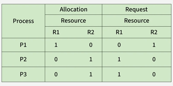
3.2.3 Need, Allocation, Max Matrices
Explanation:
Deadlock avoidance depends on three matrices:
Allocation Matrix – Resources currently allocated to each process
Maximum Matrix – Maximum resources each process may request
Need Matrix – Remaining resources required (Need = Max − Allocation)
These structures allow the OS to compute possible safe sequences and decide whether granting future resource requests is safe.
Example:
If Max = [7] and Allocation = [5], then Need = [2].
Table
| Process | Max | Allocation | Need |
|---|---|---|---|
| P1 | 7 | 5 | 2 |
| P2 | 3 | 1 | 2 |
| P3 | 9 | 3 | 6 |
Use Cases:
Banker's Algorithm safety checks
OS kernel resource allocation policies
Multi-resource transaction managers
4. Banker’s Algorithm (Core OS Deadlock Topic)
4.1 Idea and Objective
4.1.1 Why Banker’s Algorithm Is Needed
Explanation:
Banker’s Algorithm is a deadlock avoidance algorithm used by Operating Systems to ensure that resource allocation always keeps the system in a safe state. The name “banker” comes from its resemblance to how a banker manages loans: a banker will only grant a loan if doing so does not prevent all customers from eventually repaying. In the same way, the OS grants resources only if doing so allows all processes to complete without entering deadlock.
The algorithm is needed because many real-world applications request resources unpredictably during execution. If the OS blindly allocates resources, the system may transition into an unsafe state, eventually leading to deadlock. Banker’s Algorithm proactively checks whether granting a request maintains system safety.
Example:
If a process requests additional memory pages, the OS evaluates:
• “If I allocate now, will I still have enough to satisfy all other processes later?”
If yes → safe allocation
If no → request is delayed
Table
| Reason | Explanation |
|---|---|
| Avoid unsafe states | Prevent deadlocks before they occur |
| Manage dynamic requests | Processes change demands at runtime |
| Ensure fairness | Every process gets a chance to finish |
| Maintain OS stability | Predictable system behavior |
Use Cases:
Multiprogramming OS requiring strict control over resource allocation
Banking, financial, or trading systems needing strict consistency
Real-time applications where safety is more important than speed
4.1.2 Real-Time System Limitations
Explanation:
Although Banker’s Algorithm is theoretically powerful, it is rarely used in real-time systems because of strict timing constraints. Real-time applications require guaranteed worst-case execution time, which Banker’s Algorithm cannot provide due to:
• Dynamic checking of multiple states
• Matrix scanning for safe sequence
• High computational overhead
• Need for complete resource usage predictions
Real-time systems often rely on static resource reservation, priority scheduling, or lock-free algorithms instead of Banker’s Algorithm.
Example:
A real-time medical monitoring system cannot delay resource allocation just to compute safe states.
Table
| Limitation | Reason |
|---|---|
| High overhead | Matrix operations every request |
| Needs maximum future demands | Hard to predict in real-time |
| Possible delays | Violates strict timing constraints |
Use Cases:
Aerospace real-time controls
Medical embedded systems
Automotive control units
4.2 Data Structures Used
4.2.1 Allocation Matrix
Explanation:
Allocation Matrix stores the number of each resource type currently allocated to every process. It represents the current state of resource distribution in the system.
Example Matrix:
Process A B C P0 0 1 0 P1 2 0 0 P2 3 0 2
Table
| Purpose | Description |
|---|---|
| Track resource ownership | Shows how many resources each process holds |
| Used in safe-state calculation | Determines if processes can finish |
| Required by request algorithm | Ensures safe allocation |
Use Cases:
Tracking OS-level resource assignment
Detecting resource bottlenecks
Predicting safe completion sequences

4.2.2 Maximum Matrix
Explanation:
Maximum Matrix indicates the maximum number of each resource type each process may request during execution. It helps the algorithm plan future resource usage safely.
Example Matrix:
Process A B C P0 7 5 3 P1 3 2 2 P2 9 0 2
Use Cases:
Ensuring that future resource demands remain satisfiable
Preventing overcommitment of system resources
Checking safe state transitions
4.2.3 Need Matrix
Explanation:
Need Matrix is derived as:
Need = Max – Allocation
It shows remaining resources required by each process to complete execution.
Example Calculation:
Max (P0): [7 5 3]
Allocation (P0): [0 1 0]
Need = [7 4 3]
Example Matrix:
Process A B C P0 7 4 3 P1 1 2 2 P2 6 0 0
Use Cases:
Safe sequence evaluation
Preventing unsafe state transitions
Planning for resource reservation
4.2.4 Available Vector
Explanation:
Available Vector stores the number of free resources of each type. It directly influences whether a process can immediately proceed.
Example:
Available Vector:
A: 3, B: 3, C: 2
Table
| Resource Type | Available |
|---|---|
| A | 3 |
| B | 3 |
| C | 2 |
Use Cases:
Checking if demand of a process can be satisfied
Step 1 of safety algorithm
Determines system’s immediate capacity

4.3 Step-by-Step Execution
4.3.1 Work Vector Initialization
Explanation:
Work Vector represents the currently available resources during safe state analysis. Initially, it is equal to the Available Vector. As processes are assumed to complete, Work is updated by adding their Allocations.
Example:
Available = [3 3 2]
Work = [3 3 2] (initially)
After P1 completes with Allocation [2 0 0]:
Work becomes [5 3 2].
Table
| Step | Work Vector |
|---|---|
| Initial | [3 3 2] |
| After P1 completes | [5 3 2] |
Use Cases:
Safety sequence generation
Simulating process completion
Avoiding deadlock-prone allocations

4.3.2 Safe Sequence Identification
Explanation:
The safe sequence ensures that processes can finish one by one without causing deadlock. A process can finish if its Need ≤ Work. After it completes, its allocated resources are added back to Work.
Example:
Safe sequence found: P1 → P3 → P0
Table
| Process | Need | Work Check | Can Execute? |
|---|---|---|---|
| P1 | ≤ Work | Yes | Added to sequence |
| P3 | ≤ New Work | Yes | Added |
| P0 | ≤ Final Work | Yes | Completed |
Use Cases:
Resource allocation validation
Scheduling optimization
Transaction ordering
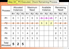
4.3.3 Example With 3 Processes & 3 Resource Types
Explanation:
Let Available = [3 3 2]
Allocation Matrix:
P0 0 1 0 P1 2 0 0 P2 3 0 2
Maximum Matrix:
P0 7 5 3 P1 3 2 2 P2 9 0 2
Need Matrix (Max – Allocation):
P0 7 4 3 P1 1 2 2 P2 6 0 0
Process Execution:
Evaluate P1: Need ≤ Available → Yes
Work becomes [5 3 2]
Evaluate P2: Need ≤ Work → Yes
Work becomes [8 3 4]
Evaluate P0: Need ≤ Work → Yes
Work becomes [8+0 3+1 4+0] = [8 4 4]
Safe Sequence:
P1 → P2 → P0
Table
| Order | Process | Work Before | Work After |
|---|---|---|---|
| 1 | P1 | [3 3 2] | [5 3 2] |
| 2 | P2 | [5 3 2] | [8 3 4] |
| 3 | P0 | [8 3 4] | [8 4 4] |
Use Cases:
Teaching deadlock avoidance
Validating multi-resource scheduling
OS kernel-level resource planning
5. Deadlocks in Real-World Operating System Environments
5.1 Deadlocks in Linux
5.1.1 Kernel-Level Deadlocks
Explanation
Kernel-level deadlocks occur inside the Linux kernel when internal components such as device drivers, file systems, or memory managers acquire multiple locks in inconsistent order. The kernel uses various synchronization primitives like spinlocks, mutexes, semaphores, and RCU (Read-Copy-Update). If these locks are taken in a conflicting sequence, the kernel enters a deadlock state affecting entire subsystems.
Kernel deadlocks are extremely serious because they can freeze the entire OS, requiring a forced reboot. Linux developers often use techniques such as lock dependency tracking, lock ordering rules, and static analysis to reduce kernel-level deadlocks.
Example
CPU 0 acquires Lock A and waits for Lock B.
CPU 1 acquires Lock B and waits for Lock A.
Kernel threads on both CPUs become blocked indefinitely.
Component Impact Table
| Component | Lock Type | Common Cause | Impact |
|---|---|---|---|
| File system | Mutex / Spinlock | Nested locking | Freeze during file operations |
| Device driver | Semaphore | Improper order | Hardware hang |
| Memory manager | Spinlock | Page fault handling conflict | Kernel stall |
Use Cases
File system metadata updates
Block device scheduling
Network subsystem resource contention
5.1.2 Semaphore & Mutex Lock Conflicts
Explanation
Linux processes often use semaphores and mutexes to access shared resources. A deadlock occurs when multiple threads lock these synchronization primitives in opposite order. Semaphores are more prone to deadlocks due to their indefinite wait behavior, while mutexes enforce stricter usage rules but can still deadlock if acquired inconsistently.
Example
Thread T1 acquires semaphore S1 then waits for mutex M1.
Thread T2 acquires M1 then waits for S1.
Both threads remain blocked.
Primitive Comparison Table
| Primitive | Behavior | Deadlock Risk | Notes |
|---|---|---|---|
| Mutex | Exclusive binary lock | High | Requires ordered acquisition |
| Semaphore | Counter-based | Very High | Can wait indefinitely |
| Spinlock | Busy-wait lock | Medium | Must not sleep |
Use Cases
Multi-threaded applications on Linux
Kernel module development
Real-time process synchronization
5.2 Deadlocks in Windows
5.2.1 I/O Subsystem Deadlocks
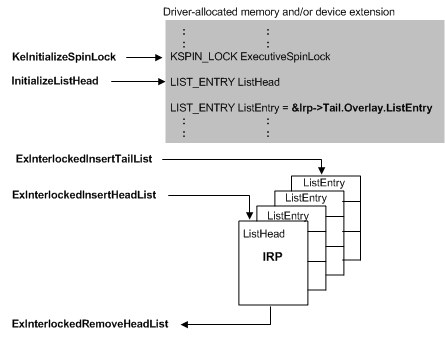
Explanation
Windows uses an I/O Request Packet (IRP) model to communicate between the OS and device drivers. A deadlock occurs when an I/O path depends on another I/O path that is blocked waiting for the first. If drivers or kernel components hold locks while processing IRPs, they may create cyclic dependencies. These deadlocks often manifest as system freezes or “Not Responding” states.
Example
Disk driver holds Lock A while waiting for a network driver.
Network driver holds Lock B while waiting for the disk subsystem.
The IRP pipeline stalls.
Subsystem Lock Table
| Subsystem | Common Lock | Cause | Effect |
|---|---|---|---|
| Disk I/O | Spinlock | Buffer conflicts | Freeze during file copy |
| Network I/O | Mutex | Packet queue serialization | Network hang |
| USB | Kernel locks | Driver misbehavior | Device stall |
Use Cases
Heavy disk I/O operations
Concurrent network + storage requests
USB device streaming
5.2.2 Memory Manager Conflicts
Explanation
The Windows Memory Manager handles page faults, virtual memory allocation, and cache operations. If two memory-intensive processes or kernel components attempt to lock memory structures like page tables or working sets in conflicting order, a memory deadlock may occur. Windows uses “acquire order” rules to reduce these conflicts, but faulty drivers can bypass or misuse them.
Example
Driver A locks the page table.
Driver B locks the working set list.
Driver A requests working set list.
Driver B requests page table.
Both remain blocked.
Memory Component Table
| Component | Locking Mechanism | Risk Area |
|---|---|---|
| Page table manager | Spinlocks | Virtual memory conflicts |
| Cache manager | Mutex | File caching deadlocks |
| Working set manager | Guarded sections | Page fault chains |
Use Cases
Memory-heavy server applications
Virtualization environments
File cache operations
5.3 Deadlocks in Distributed Systems
5.3.1 Communication Deadlocks
Explanation
Communication deadlocks occur when processes in different nodes wait for messages or acknowledgments from each other in a circular dependency. Distributed systems lack a single global clock or resource manager, so deadlocks are harder to detect. Network failures or message delays amplify this risk. In distributed computing, deadlock often arises from incorrect communication protocols, blocking RPC calls, and circular waiting across network sockets.
Example
Node A waits for response from Node B.
Node B waits for response from Node C.
Node C waits for response from Node A.
No node can progress.
Distributed Node Table
| Node | Waiting For | Resource Type | Deadlock Risk |
|---|---|---|---|
| A | B | Message | High |
| B | C | Acknowledgment | High |
| C | A | Reply | High |
Use Cases
Microservices communicating with synchronous calls
Distributed transaction management
Cluster resource allocation
5.3.2 Database Lock Deadlocks (Two-Phase Locking)
Explanation
Distributed databases use Two-Phase Locking (2PL) to maintain consistency. A deadlock occurs when transactions acquire locks in different orders across nodes. Since each transaction follows the 2PL pattern (growing phase then shrinking phase), inconsistent lock ordering creates cycles. Most modern DBMS implement deadlock detection using wait-for graphs and abort one of the transactions to break the cycle.
Example
Transaction T1 locks Row A then requests Row B.
Transaction T2 locks Row B then requests Row A.
Both wait indefinitely until DBMS aborts one.
Transaction Table
| Transaction | Lock Held | Lock Requested | Outcome |
|---|---|---|---|
| T1 | Row A | Row B | Blocked |
| T2 | Row B | Row A | Blocked |
Use Cases
Distributed SQL databases
Real-time transaction systems
E-commerce inventory updates across nodes
AlmaBetter Deadlock Resources
Introduction to Deadlock (Article/Tutorial)
This article provides a comprehensive introduction to the concept of deadlock, covering its definition, necessary conditions, and management strategies.
| Resource Type | Title | URL |
|---|---|---|
| Article/Tutorial | What is Deadlock in OS (Operating System)? - AlmaBetter | What is Deadlock in OS (Operating System)? - AlmaBetter |
Key Topics Covered
Definition: A state where two or more processes are stuck in a circular wait, each waiting for a resource held by another.
Necessary Conditions (The four conditions required for a deadlock to occur):
Mutual Exclusion
Hold and Wait
No Preemption
Circular Wait
Deadlock Management: Strategies including prevention, avoidance (e.g., Banker's Algorithm), detection, and recovery.
2. Related Concept: Semaphores (Cheatsheet)
This cheatsheet explains Semaphores, which are a tool used in Operating Systems to manage concurrent access to resources and help avoid race conditions and deadlocks (specifically in the context of mutual exclusion and resource sharing).
| Resource Type | Title | URL |
|---|---|---|
| Cheatsheet | Semaphore in Operating System - AlmaBetter | Semaphore in Operating System - AlmaBetter |
Key Topics Covered
Definition: A signaling mechanism used to coordinate activities and manage resource availability among processes.
Operations: wait() (or P) and signal() (or V).
Use Cases: Mutual exclusion and process synchronization.
Limitations: Includes a note that improper use of semaphores can result in deadlocks or starvation.


